Shot blasting wheel turbine
Cost-effective, low maintenance, highly efficient, wear-resistant, compact, and energy-saving
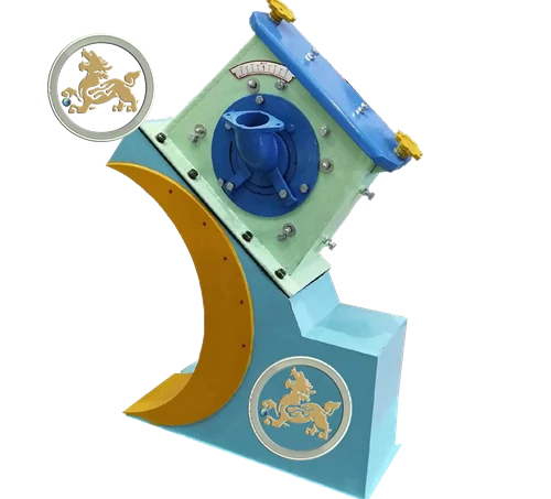
Shot blasting wheel turbine assembly is a critical component in industrial shot blasting machines, directly impacting surface preparation quality and abrasive blasting efficiency. The durability of these turbines determines the effectiveness of the shot blasting process, making them the largest consumable wear parts requiring routine maintenance. Their operational lifespan significantly influences production costs and profit margins, with proper maintenance extending machine longevity and reducing operational expenses.
Shot blasting machine performance depends on four factors: abrasive quality, projectile quantity, blast speed, and impact angle. While abrasive quality ensures consistent results, the latter three rely on industrial-grade equipment selection, precision engineering, proper installation, and optimized operation. Investing in high-quality turbines and adhering to preventive maintenance strategies enhances production efficiency, minimizes downtime, and ensures cost-effective surface treatment solutions.
Feature of the wheelabrator shot turbines:
- Compact shell structure for increased durability and extended blade lifespan, resulting in lower maintenance requirements.
- Enhanced wear resistance minimizes working noise and vibration.
- High-speed blasting capability allows for more efficient recycling of abrasives.
- Optimal blasting angle and velocity ensure energy efficiency.
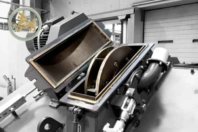
The main type of shot wheel turbines:
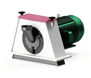
The direct-drive shot blasting turbine is a compact component within the shot blasting machine. It features a direct connection between the motor and the shot turbine via a shaft, resulting in a more compact and efficient structure. Additionally, it operates with reduced noise levels and is easy to maintain.
Typically, the direct-drive shot wheel turbine has a maximum motor power of 15kW and can achieve a blasting capacity of up to 250 kg/min.
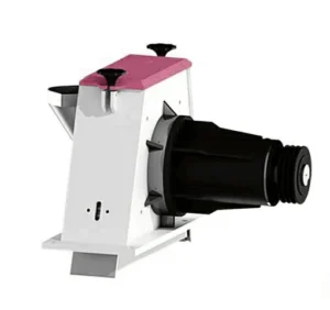
The belt-driven shot turbine is widely favored in shot blasting machines. It utilizes a belt to connect the motors and the shot wheel turbine, allowing for increased blasting flow and higher power output. This configuration ensures a stable cleaning effect.
The capacity of the belt-driven shot wheel turbine typically ranges from 15 kW to 75 kW, with a maximum blasting volume of 950 kg/min.
Spare parts for shot turbines include:
- The blades (8 pieces assembly) are precisely balanced and made of wear-resistant castings, tool steel, and tungsten carbide.
- Other components include the impeller, distributor, accelerator, and projector.
- Deflector, feed valve, cover, and shell assemblies.
- Lining, wear liner, protective plate, cover, and shell parts are present on the top, side, and end sections.
- The rotor, wheel, disc, or impeller is integral to the system.
- Feeding or supply chutes and steel shot projectors are essential elements.
- Clips and wheels are used in various mechanisms.
- Centering boards aid in alignment.
- Screws, springs, and blade clamping elements secure components.
- The wheel cover consists of body, side, cover, and clips.
For more detailed information…
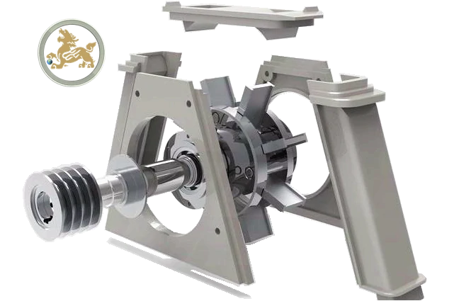
The working principle of shot wheel turbine assembly:
- Abrasive Feed and Rotation:
Steel shots or shot grit enter the impeller through the abrasive feed chute. The impeller and blades self-rotate continuously at a high speed, driven by either a direct-connect or belt-connected motor. The steel shots pass through the impeller and deflector, propelled by the rotating blades. The blades push the high-speed shot steels out from the bottom opening of the shot wheel turbine shell. To ensure effective shot blasting, the impeller, deflector, and blades need to be adjusted to the correct angle and projectile speed. The shot abrasive flow should primarily impact the workpieces, with a focus on the protective plates in the first impact area.
- Abrasive Circulation System:
The shot blast wheel assembly unit projector’s disk contains the abrasive, which eventually descends by gravity and collects in a hopper located at the bottom of the shot blasting room. A screw conveyor transfers the shot steel to the boot of a bucket elevator. Wearing-resistant rubber belts equipped with buckets lift the shot abrasives to the desired height. The elevator belt’s tensioning arrangement device is conveniently located at the bottom, ensuring no spillage of the belt.
- Abrasive Purify System:
Oversize contaminants and the abrasive mixture are discharged from the top section of the bucket elevator into a magnetic separator via an upper screw conveyor. After three stages of magnetic separation, the abrasive mixture is classified. Trashes are directed to a trash drum for discharge, fine dust particles are conveyed through vent piping to the dust collector, and the useful shot steels drop into a reuse hopper. From there, they are directed to the abrasive feed valve, which is controlled by pneumatic electromagnetic valves.
